Remote Sampling Strategy
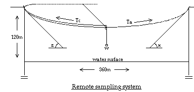
In light of the riskiness of a climbing descent a remote strategy was used to collect lake samples. A 3-D perspective schematic of the remote sampling system is shown below. The system features a 402-m-long 14 gauge fencing wire spanning a crater and serving as the primary support for the sampling line. This support cable was carefully strung over TAP during the afternoon of August 16 and later over TiN on August 21. Numerous small bushes lining the TAP crater rim hindered the process, while the deep notches surrounding the TiN crater slowed the transplanting of the cable from the first lake to the second. Onto the support cable a series of two pulleys was attached.

The upper pulley rolled smoothly along the support and ferried the sampling line out over the lake by the force of gravity acting on the weight of the sampling bottle assemblage. To retrieve the pulley a 305m 80lb. test nylon-coated stainless steel wire bound to it was reeled in using a model 113 Penn Senator(R) reel. The lower pulley was connected to the upper pulley by a locking carabiner which allowed for a 90 deg offset and some free rotation. The sampling line itself was a 305m 210lb. test stainless steel braided wire spooled onto a modified trawling downrigger. This line was fed through the lower pulley and connected beyond it to the instruments.
According to elementary physics the tension resulting from the weight (w) of the sampling bottle assemblage, sampling line, and support cable on the support cable is divided into three vectors. Ignoring the third dimensional force (going into the page in the schematic), the tension on the cable resolves into Ta and Tc, where
- Ta = f(w,sin x)
- Tc = f(w, sin z)
Given a weight of 50lbs. and an angle x = z = 30 deg, the total tension on the support cable equals Ta + Tc = 200lbs. In practice, applying more weight actually increases the angle so if 60lbs. were used and the angle was therefore increased to 37 deg then the total tension would still equal 200lbs. The delicate balance of weight and angle combined with some incalculable parameters including the angles x and z (which also change as the pulley moves out over the lake) and the support cable's tensile strength made any exact theoretical design impossible to implement. Nevertheless the underlying tensile warnings were heeded and the system worked as described for several days.


